Case Study Overview
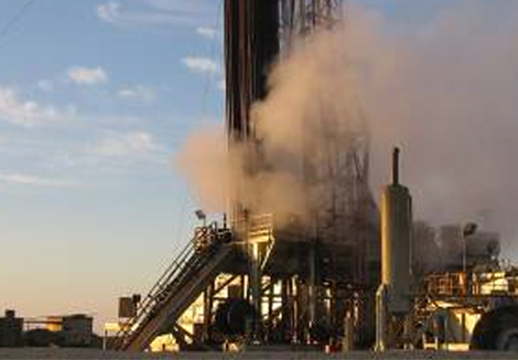
CWC was dispatched to a surface blowout that occurred while the rig was tripping out of the hole with a 3 ½” tubing and a test packer. The well began to flow and the drilling crew made several attempts to install the kelly that were unsuccessful. The driller was unable to move the pipe in either direction as the packer had set prematurely at 2,400’. The flow became so strong after unloading the completion fluid that the rig crew was forced shut down the engines and abandoned the rig.

Situation Upon Arrival
CWC personnel found during the initial assessment that the well was discharging natural gas and condensate approximately 50’ into the air from the 3 ½” tubing string sitting in the slips on the rig floor. There was 3,100 psi on the annulus under the pipe rams that would not bleed off. This indicated that the packer did not completely seal off the backside and that opening the bonnet doors to install shear rams was not an intervention option. The rig crew had unsuccessfully attempted to stab the and it was resting on the shoulder of the tubing stub in the rotary table. This dispersed the flow and created a large gas cloud that limited visibility on the rig floor. The derrick was filled with the work string that limited working room on the rig floor. A large pool of condensate had formed on location.
Intervention Strategy
An intervention plan was formulated with the ultimate goal of capping and securing the well by bullheading fluid followed by cement. The following milestones were identified for the intervention plan.
- Jet cutting the tubing sticking through the rotary table
- Preparation and skidding the rig for skidding off of the well.
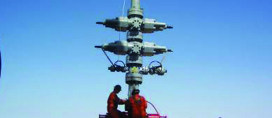
- Preparation of the BOP for capping after skidding.
- Capping, killing ad securing the well.
- Removing the substructure, without damaging the wellhead integrity and avoiding igniting the well, would pose the greatest obstacles during the intervention operations.
Operations
A snatch block and 1” cable were attached to the fast line of the drawworks in order to pick up the traveling block and lift the kelly up off the joint of pipe in the rotary. The kelly was secured to the derrick leg. The auxiliary rig equipment, mud pumps and pits were removed from location. The substructure was prepared for skidding by removing the dessert tires, catwalk, v-door, and front stairs, mouse hole casing and kelly shuck.
The bell nipple was unbolted and secured to the underside of the rig floor exposing the 3 ½” for cutting operations. The cross support beams on the substructure were removed to avoid damaging the wellhead. CWC’s single jet cutter was rigged up and used to severe the pipe above the annular preventer.

The rig was skidded using two two traveling blocks and a deadman system strung together with 1 ⅛” drill line. After removing the annular BOP the tubing was again jet cut approximately 6” above the rig’s double BOP to allow for the capping stack to be spun on over the flow.
The well was then capped. The blind rams were closed and the kill operations began by pumping water down the tubing. A cement slurry was then pumped after the water. CWC was released during a second cementing stage.